
Nuclear engineering, Model development, Model evaluation, Lumped parameter, Continuous simulation
ABSTRACT
The paper presents the mathematical model and thermal-hydraulic analysis of CANDU Shutdown Cooling System (SDCS). The mathematical model for the SDCS equipments was developed. Initially these mathematical models were coded in ACSL simulation language then have been implemented in the Modular Modeling System (MMS) code using the CompGen tools. There are two options for the SDCS operation with different flow path configuration. Essentially, for each option, the thermal regime is time dependent but the flow regime is time independent. Therefore, for the thermal-hydraulic analysis of the system two steps were used. In the first step the flow along the system pipes was determined for each operation stage with the PIPENET code. Subsequently, in the second step, the models developed were used to predict the thermal behavior of reactor core. The results obtained for the cooling of the Primary Heat Transport System (PHTS) from 177°C to 54°C are presented.
INTRODUCTION
After the reactor shutdown, the fuel continues to generate heat by decay of fission products. Normally the initial cooldown of the primary heat transport system (PHTS) is accomplished by using the steam generators. However, at temperatures below 177°C this process becomes ineffective.
The Shutdown Cooling System (SDCS) (CITON, 1990) is provided to remove decay heat from the reactor during shutdown and to cool the PHTS from 177°C to 54°C and hold the system at 54°C for an indefinite period of time. The Candu system consists of a pump and a heat exchanger at each end of the reactor. The design is such that cooldown can be achieved using either the heat transport pumps (flow direction is from inlet headers to the outlet headers via SDC heat exchanger and the SDC pump bypass) or using the shutdown cooling pumps (flow direction is from outlet headers to the inlet headers, see fig. 1) (AECB, 1993). In both cases, the pressure at the inlet headers is sufficient to force water through the core to the opposite outlet headers.
There are two cooldown options for circulating the D O: by using the Primary Heat Transport Circulating Pumps, or by using the Shutdown Pumps. The initial phase of the two options is similar and involves the use of PHTS pumps to circulate the coolant through the steam generators to lower the PHTS system temperature from 260°C. After the initial cooldown phase, cooldown using PHTS pumps and the SDC heat exchangers can be initiated from a HT system temperature of 177°C (option 1). However, it only reduces the HT system temperature effectively to 121°C with four HT pumps being used or 88°C with two pumps being used. Further cooldown has to be carried out through the use of the SDC pumps and heat exchangers (option 2).
Thermalhydraulic analysis of SDCS must certify that the system is able to remove the decay heat from the fuel following normal shutdown and after certain accident conditions (e.g. feedwater line break). This analysis requires the flow rate and temperature calculation along the systems equipments. However, the physical characteristics of the SDCS show that the momentum and energy balance equations can be decoupled. Consequently, for each system option (different flow path configuration) the flow rate is first calculate. Knowing the flow rate, the temperature distribution can be now evaluated. The paper underlines the SDCS model development and results obtained for the cooling of the Heat Transport System (PHTS) from 177°C are presented.
Different system operation stages have different flow paths. However, the hydraulic resistance of the SDCS loop does not change during system operation for each stage. This fact permits to decouple the momentum balance equation from the energy balance equation. Thus, the flow rates along the SDCS loop can be calculated first for each system operation stage. These calculations are doing with the PIPENET code (Sunrise Systems Limited, 2000). It can performs pipe sizing and pump selection calculations in the steady state, and unsteady flow problems such as water hammer, control systems and hydraulic forces for pipe stress analysis. PIPENET has also a standard module for solving general flow problems with liquids, gases or steam - in pipe and duct networks - cooling water systems, steam distribution systems, HVAC systems.
Figure 1 shows the PIPENET flowchart for option 2 of SDCS configuration, e.g. cooldown has to be carried out through the use of the SDC pumps and heat exchangers.

Figure 1: CANDU-6 Shutdown Cooling System
Figure 2: PIPENET Flowchart for Shutdown Cooling System
The flowrate obtained this way is used further in the thermal analysis of the system.
The thermal model consists in modeling the thermal behavior of the following SDCS components: nuclear reactor, steam generators, water-to-water heat exchangers, pumps, and pipes. The analyze scope was to investigate cooling capability of the SDCS in all operating regimes. Consequently all heat sources of the system must be included in the analysis. This includes the reactor decay heat, and stored energy in fuel, pipes and coolant. The heat sinks include the steam generators secondary side (for cooling down from operating condition to 177°C) or the heat exchanger cooling water. The main aspects of the mathematical model for the SDCS equipments are outlined in the following.
CANDU is a pressurized water reactor developed by AECL in
When the reactor is shut down, modeling of the neutronic behavior is not needed. Thus, the mathematical model of the reactor consists in energy balance equation for the fuel and coolant. The heat sources are represented by the decay heat and the energy stored in the fuel and fuel channels wall. The axial power distribution in fuel channel is supposed to be cosinusoidal as the reactor shutdown did not distort the nominal neutronic flux distribution. For the decay heat an analytical expression given in (Toderas 1993) was used.
The energy balance equation for fuel and coolant are written for a mean fuel channel with the average reactor power and flow rate. Thus, the energy balance equation can be written for the UO2 fuel pellet and fuel clad as:
![]()
(1)
 (2)
(2)
and for the coolant as:
 (3)
(3)
However, the fuel clad is thin and has a relatively high thermal conductivity. Thus, a steady-state equation can be used instead of equation (2). Solving for clad temperature from the steady-state form of the eq. (2), and introducing corresponding value in eqs. (1) and (3) we obtain the following set of differential equations:
![]() (4)
(4)
 (5)
(5)
 (6)
(6)
where
![]() (7)
(7)
For the fuel channel wall, the energy balance equation is written as:
![]() (8)
(8)
Thus, the thermal model of the nuclear reactor is given by the equations (4), (5), (6) and (8). These equations are solved spatially first by integrating along fuel channel length. As a result a set of ordinary differential equations are obtained. Further, the time integration of these equations provides the temperature behavior of fuel, coolant and fuel channel wall.
Heat exchanger model
The heat exchanger is a tub-shell, water-water type. A lumped parameter model is used for the heat exchanger model (Danila, 1989). The flow is incompressible, thus the low rate is constant along the heat exchanger. The energy stored in the tube wall is neglected. The energy balance equations are written for the heat exchanger outlet temperatures. These are:
![]() (9)
(9)
![]() (10)
(10)
where the heat exchanged between fluids is (Frass, 1965):
![]() (11)
(11)
Only the flow rate is considered to influence the overall heat exchange coefficient.
Pipe model
The main phenomena that must be modeled, from thermal analysis of SDCS point of view, are represented by heat stored in coolant and pipe wall, and the heat loss trough pipe wall. Thus the main pipe model equations are the energy balance equations for the coolant and for the pipe wall. These equations are:
![]() (12)
(12)
![]() (13)
(13)
The heat exchanged between coolant and pipe wall is calculated similar to the HE model. The heat stored in the pipe wall has a important contribution to the heat sources during the shutdown cooling process.
Steam generator model
The steam generators (SG) are not a SDCS components. However, to simulate the entire cooldown process, starting from the reactor shutdown at nominal condition, a SG model is needed. A detailed SG model was developed for the simulation of the primary or secondary side of the CANDU plant (Prisecaru, 2004). This model is already implemented in the MMS code. Nevertheless, the operational regime of the SG for cooldown process did not require a detailed model. Hence, a simplified model was developed. For regimes involved in cooldown process, the steam generators look like heat source instead of heat sink. A fraction of 55% from coolant flow rate bypasses the reactor core trough SG. As there is not a heat removal on the secondary side of SG, and the pressure of secondary fluid is held constant, the coolant heats up trough SG. Thus, the steam generators became an important heat source after the reactor shut down. The energy balance equations are:
 (14)
(14)
 (15)
(15)
In the overall heat transfer coefficient calculation, the tube side heat transfer coefficient is considerate flow dependent whereas the shell side heat transfer coefficient is temperature dependent (Collier, 1994). The energy stored in the SG tube wall was neglected, because this amount is small compared with the energy stored in the secondary side of the SG.
Pump model
From the thermal point of view, the pump looks like a heat source due to frictional forces. Thus, the temperature of the coolant leaving the pump is dependent on pumps power and pump efficiency:
 (16)
(16)
Initially these mathematical models were coded in ACSL simulation languages (MGA, 1993). The ACSL coded program was used for the validation of the mathematical models. Afterward, the models have been implemented in the Modular Modeling System (MMS) code using the CompGen tools (Framatome Tehnologies, 1998a, 1998b). All the cooldown regimes have been simulated. In the following, the cooldown from the 177oC is presented.
For this simulation the SDCS pumps and heat exchangers models were used. Some of the results are presented in the figures 3 and 4. The coolant temperature at the outlet of heat exchanger are below 85oC from the beginig of simulation even for a flow rate in the heat exchanger shell side of about 40% of nominal value. Hence, the cooldown rate at the outlet of reactor was below prescribed value of 2.8oC/min during all transient. After about 14000 s, temperatures in the SDCS are established to about 35oC at steam generator outlet (reactor inlet) and about 85oC at reactor outlet.
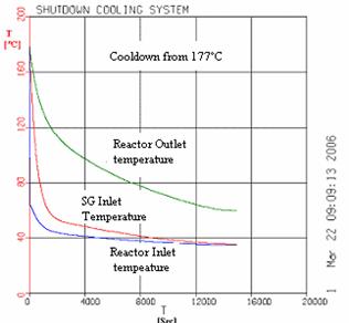
Figure 3: Coolant Temperature at Reactor and SG
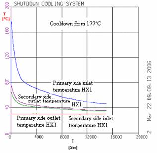
Figure 4: Tube and Shell Side Heat Exchanger Temperature °C
CONCLUSIONS
In this paper mathematical models for the components of the Shutdown Cooling System with application to the Cernavoda N.P.P. are presented. The main aspects of the mathematical model are highlighted. The mathematical models have been coded in ACSL, and after models validation the models are implemented in the MMS code using the CompGen tools. The analyzes were made in porpoise of verifying the capability of Shutdown Cooling System to cool down the Primary Heat Transport System.
Analyze consists in several hydraulic and termohidraulic analyzes. In this paper we presented just a short brief of this regimes. The operating regimes analyzed were the following:
Hydraulic analyze:
initial hydraulic regimes for cool down from 149˚C, 177˚C, and respectively 260˚C to cold state using Primary Heat Transport System (PHTS) pumps;
initial hydraulic regimes for cool down from 149˚C, 177˚C, and respectively 260˚C to cold state using Shutdown Cooling System (SDCS) pumps;
initial hydraulic regime for cooling down of PHTS drained using SDCS from 77°C to zero power cold state.
Thermal-hydraulic analyzes:
normal operating regimes
cooldown regimes using PHTS pumps starting from 149˚C, and respectively 177˚C;
cooldown regimes using SDCS pumps starting from 121˚C, 149˚C, and respectively 177˚C;
cooldown regimes using SDCS pumps starting from 77˚C, and PHTS drained to zero power cold state.
abnormal operating regimes
cooldown regimes using PHTS pumps starting from 260˚C;
cooldown regimes using SDCS pumps starting from 260˚C
Analyzing the parameters evolution from the system for all stationary and transient regimes analyzed we observed that all values obtained for thermo hydraulic parameters and time period up to reaching stational regimes of the system are close, in a range of 3%, to technical specifications of design project of the system. Cook down speed was under the value of 2.8˚C/min for normal operating regimes. This value was over-passed just in abnormal operating regimes.
REFERENCES
Atomic Energy Control Board (AECB), 1993. Fundamentals of Power Reactors - Module Two: Nuclear Systems. Training Manual.
Center for Engineering and Technology for Nuclear Objective (CITON). 1990 Shutdown Cooling System Technical Description Manual
Collier, J.G.; and J.R.Thome. 1994. Convective Boiling and Condensation, Clarendon Press.
Danila N.; and
Framatome Tehnologies. 1998a. MMS Theory Manual Release 5.1.
Framatome Tehnologies. 1998b. CompGen Users Manual.
Frass, A.P.; and M.N. Ozisik. 1965. Heat Exchanger Design, John Wiley & Sons,
Inc.,
Mitchell and Gauthier Associates (MGA) Inc. 1993. Advanced Continuous Simulation Language (ACSL) Reference Manual. Edition 10.1
Prisecaru,
Sunrise Systems Limited. 2000 PIPENET Users Manual
Todreas,
N.E.; and M.S. Kazimi 1993, Nuclear Systems, Thermal hydraulic Fundamentals,
NOTATION
cp - heat capacity, J/kg oC
h - heat transfer coefficient, W/m2 oC
P - power, W
Q - thermal power, W
q power density, W/m3
r - radius, m
S - surface, m2
T - temperature, oC
U - overall heat transfer coefficient, W/m2 oC
V - volume, m3
W - flow rate, kg/s
w - velocity, m/s
DT - mean logaritmic temperature difference, oC
r density, kg/m3
h - efficiency
c - coolant
e - outlet
f - fuel pellet
fs - fuel pellet to clad
i - inlet
pmp - pump
s - fuel clad
sh - shell side
sSG - SG secondary side
t -tube side
w - pipe wall
|
Politica de confidentialitate |
| Copyright ©
2024 - Toate drepturile rezervate. Toate documentele au caracter informativ cu scop educational. |
Personaje din literatura |
| Baltagul caracterizarea personajelor |
| Caracterizare Alexandru Lapusneanul |
| Caracterizarea lui Gavilescu |
| Caracterizarea personajelor negative din basmul |
Tehnica si mecanica |
| Cuplaje - definitii. notatii. exemple. repere istorice. |
| Actionare macara |
| Reprezentarea si cotarea filetelor |
Geografie |
| Turismul pe terra |
| Vulcanii Și mediul |
| Padurile pe terra si industrializarea lemnului |
| Termeni si conditii |
| Contact |
| Creeaza si tu |