Oscilatoare Butler
Oscilatorul Butler, la o privire superficiala, arata ca si un oscilator Colpitts (vezi fig. 32). Diferenta consta in faptul ca intre reteaua de reactie si emitorul tranzistorului este conectat cristalul de cuart. Aceasta schema particulara reprezinta un oscilator ce foloseste rezonanta serie a cristalului. Pentru o amorsare sigura a oscilatiilor si pentru a minimiza puterea disipata pe cristal, rezistenta R1 se alege intre 100 si 1000 de ohmi. In cazul in care oscilatorul functioneaza in gama de la 3 la 10 MHz, se recomanda: C1=47 pF, C2=390 pF, iar pentru gama de la 10 la 20 MHz: C1=22 pF, C2 = 220 pF.
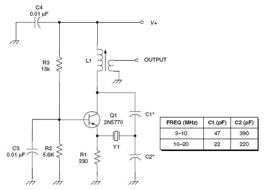
Fig. 32 Oscilator Butler
Circuitul oscilant de la iesire poate fi acordat combinat, prin intermediul lui C1 si L1. Aceasta schema poate oscila si cu cristalul scurtcircuitat si trebuie sa ne asiguram ca frecventa de oscilatie "libera" este aceeasi cu frecventa de rezonanta a cristalului. Cu cristalul in circuit, acesta schema poate asigura o stabilitate de 10 la 20 ppm daca semnalul se preia prin intermediul unui etaj separator cu impedanta mare de intrare si care sa asigure o buna izolare a oscilatorului fata de sarcina propriu zisa. Altfel, poate sa apara o tarare a frecventei in functie de sarcina.
In fig. 33 este prezentata o schema mult mai complexa a unui oscilator Butler care, uneori, mai este numita si schema de oscilator aperiodic cu cuart. In aceasta schema se folosesc doua tranistoare suplimentare pentru a asigura separarea, unul dintre acestea fiind folosit si ca parte a circuitului de reactie. Gama de frecvente in care poate functiona se intinde de la 300 kHz la 10 MHz, cu o selectie corespunzatoare a tranzistoarelor.
Unele cristale de joasa frecventa prezinta o rezistenta echivalenta serie mica mai degraba la una din frecventele inalte in modul overtone de oscilatie, decat in modul fundamental, ceea ce determina schema sa oscileze pe o frecventa nedorita. Solutia prevenirii acestei situatii consta in folosirea unui tranzistor cu un produs castig-banda scazut (de exemplu 2N3565 sau un echivalent).
Schema din fig. 33 genereaza la iesire o forma de unda sinusoidala, dar nu lipsita de componente armonice. In particular, mai ales armonica a doua si a treia sunt evidente. Totusi, daca armonicele sunt dorite (atunci cand oscilatorul este utilizat ca circuit de multiplicare a frecventei), putem genera armonici puternice pana la 30 MHz folosind un cristal cu frecventa de 100 kHz, daca R5 este micsorata pana la 1000 de ohmi.
Iesirea acestui oscilator se asigura prin intermediul unui etaj separator repetor pe emitor, caracterizat printr-o impedanta mare de intrare si o impedanta mica de iesire. In general, pentru a reduce incarcarea oscilatorului si a uniformiza variatia sarcinii, se recomanda ca iesirea oricarui oscilator de radiofrecventa sa se asigure prin intermediul unui etaj separator, repetorul pe emitor putand fi utilizat ca in majoritatea cazurilor.
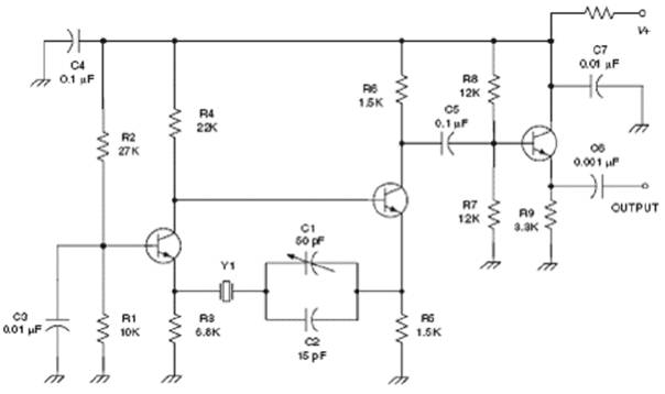
Fig. 33 Oscilator Butler aperiodic, cu etaj separator
Dupa cum am mentionat mai sus, oscilatoarele Butler folosesc rezonanta serie a cristalului. Introducerea unei capacitati de sarcina serie cu cristalul (vezi fig. 33) da posibilitatea utilizarii rezonantei paralel, cu un reglaj fin al acesteia prin intermediul trimerului C1. Prin scurtcircuitarea acestei capacitatii se revine la modul serie de functionare a cristalului.
Colpitts oscillators
The Colpitts oscillator is characterized by a feedback network consisting of a tapped
capacitive voltage divider. In Fig. 15 the feedback is provided by C1 and C2, although
the situation is somewhat modified by the gate capacitances of Q1. This circuit can be
used with parallel mode crystals from about 3 to 20 MHz with proper values of C1 and C2
(see table provided in Fig. 15). Frequency trimming of the oscillator can be done by
shunting a small value trimmer capacitor across the crystal. The trimmer can also be
placed in series with the crystal.
If the oscillator tends to oscillate parasitically in the VHF region, then try using the
snubber resistor method (R4 in Fig. 15). This could occur because the JFET used at Q1
will have sufficient gain at VHF to permit Barkhausen to have his due at some frequency
where strays and distributed L-C elements produce the correct phase shift. A value
between 10 and 47 ohms will usually eliminate the problem. Alternatively, a small ferrite
bead can be slipped over the gate terminal of Q1 to act as a small value VHF/UHF RF
choke.
Figure 16 is very similar to Fig. 15, except for two features. First, the active device
is an n-channel MOSFET rather than a JFET. Any of the single-gate devices (e.g. 3N128)
can be used. One must, however, be mindful of the possibility of electrostatic damage
(ESD) when the MOSFET is used.
The other difference is that a 1N4148 small-signal diode shunts the gate-source path to
provide a small amount of automatic gain control action. When the signal appearing
across the crystal and feedback network is sufficiently large the diode will rectify the
signal and produce a DC bias on the gate that counters the source bias provided by R2.
This diode helps smooth out amplitude variations, especially when more than one crystal
is switched in and out of the circuit.
Another variation on the Colpitts theme is the impedance inverting oscillator circuit of
Fig. 17. It will provide stability of 10 ppm over a wide temperature range (0°C to 60°C)
if a wise selection of components is made (C1-C3 and L1 are particularly troublesome).
The circuit will also remain within ±0.001 per cent over a DC power supply variation of
2:1 (provided the crystal dissipation is not exceeded). Harmonic output of the circuit is
typically low.
The oscillation frequency is set by adjusting inductor L1. The turns counts shown in the
table in Fig. 17 presume a 5 mm slug-tuned coil form designed for use in the frequency
range 3 to 20 MHz. Some experimentation is needed depending on the particular former
used. The idea is to set the resonant frequency of the coil and C1-C3 combined to
something near the crystal frequency.
It is sometimes appealing to add a tuned circuit to the output circuit of oscillators. The
harmonics of the oscillator are suppressed when this is done. But in this case, a transistor
equivalent of the old-fashioned TGTP oscillator will result because of the action of the
output-tuned circuit and the L1/C1-C3 combination. Don't do it!
Overtone oscillators
Thus far only the fundamental oscillating mode has been discussed. But crystals oscillate
at more than one frequency. The oscillations of a crystal slab are in the form of bulk acoustic
waves (BAWs), and can occur at any wave frequency that produces an odd halfwavelength
of the crystal's physical dimensions (e.g. 1_/2, 3_/2, 5_/2, 7_/2, 9_/2, where
the fundamental mode is 1_/2). Note that these frequencies are not harmonics of the
fundamental mode, but are actually valid oscillation modes for the crystal slab. The
frequencies fall close to, but not directly on, some of the harmonics of the fundamental
(which probably accounts for the confusion). The overtone frequency will be marked on
the crystal, rather than the fundamental. It is rare to find fundamental mode crystals
above 20 MHz or so, because their thinness makes them more likely to fracture at low
values of power dissipation.
The problem to solve in an overtone oscillator is encouraging oscillation on the correct
overtone, while squelching oscillations at the fundamental and undesired overtones.
Crystal manufacturers can help with correct methods, but there is still a responsibility on
the part of the oscillator designer. Figure 18 shows a third-overtone Butler oscillator that
will operate at frequencies between 15 MHz and 65 MHz. The inductor (L1) is set to
resonate close to the crystal frequency, and is used in part to ensure overtone mode
oscillation. If moderate DC supply voltages are used (e.g. 9 to 12 volts in most cases), the
harmonic content is low (-40 dB), and stability is at least as good as a similar fundamental
mode Butler oscillator.
Figure 19 is a third-overtone impedance inverting Colpitts style oscillator that will
operate over the 15 MHz to 65 MHz range. As in similar circuits, inductor L1 is tuned to
the overtone, and is resonated with C1 (combined with the capacitances of C2 and C3).
Values for C1 through C3, and winding instructions for a 5 mm low-band VHF coil
former are shown in the table.
Note the resistor across crystal Y1. This resistor tends to snub out oscillations in modes
other than the overtone, including the fundamental. Care must be taken to not make L1
too large, otherwise it will resonate at a lower frequency (with C1-C3), forming an
oscillator on a frequency not related to either the crystal's fundamental or overtones. The
oscillator may well be perfectly happy to think of itself as a series-tuned Clapp oscillator!
Operation of this circuit to 110 MHz, with fifth- or seventh-overtone crystals, can be
accomplished by modifying it to the form shown in Fig. 20.
Figure 19 Third overtone Colpitts oscillator.
Frequency stability
An ideal sine wave RF oscillator ideally produces a nice, clean harmonic- and noise-free
output on a frequency that is stable, but real RF oscillators tend to have certain problems
that deteriorate from the quality of their output signals. Load impedance variation and
|
Politica de confidentialitate |
| Copyright ©
2025 - Toate drepturile rezervate. Toate documentele au caracter informativ cu scop educational. |
Personaje din literatura |
| Baltagul caracterizarea personajelor |
| Caracterizare Alexandru Lapusneanul |
| Caracterizarea lui Gavilescu |
| Caracterizarea personajelor negative din basmul |
Tehnica si mecanica |
| Cuplaje - definitii. notatii. exemple. repere istorice. |
| Actionare macara |
| Reprezentarea si cotarea filetelor |
Geografie |
| Turismul pe terra |
| Vulcanii Și mediul |
| Padurile pe terra si industrializarea lemnului |
| Termeni si conditii |
| Contact |
| Creeaza si tu |