
Water hammer in nuclear installations. cASE study in feed water system.
Abstract
Hydraulic hammer and adverse effects are presented extended in literature available for those who operates and design installations in which this phenomena's occurs.
There are specialized computational programs which evaluates on divers technical aspects which occurs with this phenomenon are today available for technical personal.
There can be noticed that not all technical characteristics and not all effective operating modes which are in the work of this paper are not covered by existing computational programs elaborated by specialized software developers; besides even specialized developers of this programs recommends with insistently that computational results offered by specialized programs to be verified by specialized technologist with experience in alternative theoretical computations in order to avoid any misinterpretation of results obtained by computational codes.
After selective
exposures of theoretical fundamentals of the problem there are presented a
computational calculation obtained using specialized calculation code PIPENET
(Sunrise System Limited,
In a first stage we get the elastic characteristic of pipe where the phenomena of hydraulic hammering take place and there are derivative descriptions of differential equations which describe physical phenomena.
The second part there we fulfill a complete system analyze of water hammer effect due to a fail close of the four level control valves of Steam Generators.
We compared the highest attended pressure with design pressure of the system. We observed that the design pressure is not over-passed.
We concluded that the system is well design against water hammer due to the initial event analyzed.
Introduction
This paper presents an approach to water hammer phenomena that occurs in nuclear and non nuclear installations. We will make at the first an introduction to water hammer theory - then an well know application of water in a forced pipe. This is done in order to observe - calibrate the PIPENET response compared with a known situation that occurs in hydraulic installations. At the end we made an application on a transient regime in a feedwater system. The regime is initiated by close of all level control valves of steam generators. Analyze are made in two cases: in the first case the head limiter of main pumps are unavailable; in the second case the head limiter of main pumps are available. We compared the pick pressure from the system with design pressure.
Water-hammer - Theory
The standard theory of water hammer is based on two fundamental correlations:
Computation of fluid pressure wave
Computation of fluid speed.
In order to obtain this
correlations we start from second
![]() (1)
(1)
The trace on Ox ax of this is:
![]() (2)
(2)
Simplifying and taking
in consideration of ![]() ,
,
![]() (3)
(3)
This is cinematic correlation, the first correlation between V(x,t) and y(x,t)
The volume variation during water hammer is:
![]() (4)
(4)
Figure 1. Volume variation during water hammer phenomena
Total volume variation is given by:
 and it represents total volume increase.
Volume rise is given by the correlation
![]() (5)
(5)
Volume contraction due to pressure rise is:
![]() (6)
(6)
The minus sign indicates that at a pressure rise we will have a decrease of the volume.
Continuity equation is
![]()
This can be simplified as:
![]() (7)
(7)
Where
![]() (8)
(8)
The water hammer phenomena respects the vibrant cord correlation of
 (9)
(9)
And partial derivation equation (3)and (7):
![]()
![]() (10)
(10)
Through integration by replacing variables (Euler and D'Alambert) with change of variables
![]() (11)
(11)
We obtain the canonic for equation (9)
![]()
Or
 (12)
(12)
Going back to initial variable we obtain and deriving by variable x Allievi correlations:
![]() (13)
(13)
![]() (14)
(14)
where y is pressure value, y0 - initial pressure value, t - time, a - wave speed in fluid, g - gravitational acceleration, F - direct function of water hammer, f - indirect function (reflected - inverse) of water hammer.
The
maximal overpressure is calculated before indirect wave is produced therefore
in this situation of f s 0 and ![]() where L represents the
length of the pipe from suction area to closing valve. If the valves is closing
in interval
where L represents the
length of the pipe from suction area to closing valve. If the valves is closing
in interval ![]() results that at the
point
results that at the
point ![]() and
and ![]() the maximal rise of
pressure is given by Jukovik correlation:
the maximal rise of
pressure is given by Jukovik correlation:
![]() (15)
(15)
where r is bulk density of the fluid, a - wave speed in the fluid, V0 - fluid speed not perturbed by valve closing process.
Usual calculation is consisted of determination of functions F and f at the first step of calculation. These values obtained at the first step are used as initial data for the next iteration step.
After the computation of the first is made we will get other values for the analytical functions F and f as well for pressure and speed. These values are initial values for next iteration steps.
The iteration time step should be enough small in order to assure mathematical stability of numerical method utilized and in the same time should be correlated with closing valve stroking time.
Practical calculation method eliminates the function f based on the fact that it is equal with the value of function F at the previous computational step so that the computation is simplified to determining the function F.
This computation method does not take in consideration fluid viscosity and so there is no amortization in pressure oscillations obtained by this method. Pressure waves obtained in this method are propagated infinitely. This inconvenient can be overcame by taking in consideration fluid viscosity. This problem is solved in PIPENET computational method.
In the next figure we illustrated the pressure resulted in the standard problem of water hammer - closing of a valve from a forced pipe. The results were compared with known results from technical books. The results were under 2% difference - the differences are mainly generated by the fact that PIPENET program take in the consideration the damp due to fluid viscosity and the difference between speed of sound and pressure wave in the fluid.
The work case:
- Speed of fluid: 2.5 m/s;
- Head rise in forced pipe: 150 m;
- Pipe diameter: 1.600 m;
- Pressure drop is located in valve;
- Closing time of valve: 3.2 seconds;
- Transients started at 5 seconds from the start of the analyze
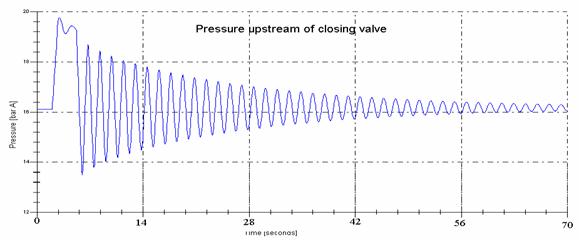
Figure 2. Water hammer application in a forced pipe
The pick pressure was about 19.5 bar (g) obtained 1 second after the transient started.
Figure 3. Theoretical computation result for Alievi corelations
Application of water hammer on Feed water system
We took in consideration the feed water system. The limits of the system were:
- Upstream: Deaerator
- Downstream: Steam Generators
Transient are generated by closing the all four steam generator level control valves. Stroking time of these valves is considered to be 20 seconds.
The analyze is started from nominal operating condition of feed water system - 2 main pumps in operating and one stand by pump with heating line opened.
The system flow diagram is presented in figure 4. The computational diagram is shown in the figure 5.
The computation took in consideration two cases:
the head limiter of feed water pump unavailable;
the head limiter of feed water pump available;
The analyze purpose was to observe the pick pressure generated by the water hammer transient and to compare it with the design pressure of the system.
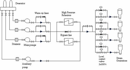
Figure 4. Feed water System specific to CANDU 6 from NPP Cernavoda
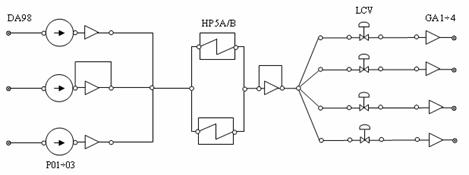
Figure 5. Feed Water system - computational diagram
The computation took in consideration two cases:
the head limiter of feed water pump unavailable;
the head limiter of feed water pump available;
The analyze purpose was to observe the pick pressure generated by the water hammer transient and to compare it with the design pressure of the system.
Figure 6 and 7 present the maximum pressure from the system. These values are obtained at the inlet point of the level control valves.
The main difference form these two analyze was the fact that in the second one the pumps are stopped about 14.5 seconds from the beginning of water hammer transient due to high pressure in discharge pipe. The discharge pressure of the pumps starts to decrease function of angular impulse of the pump. In order to supply this value we had to make an equivalent
impulse of main pump, booster pump and theirs motors.
The pick pressures in analyze were:
about 100 bar (g) for the first case;
about 90.5 bar (g) for the second case.
Comparing the design pressure of the system with computational results we conclude that the head limiter is a very important component of the system.
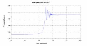
Figure 6. Pressure pick upstream of Steam generator level control valves - head limiter of main pumps unavailable
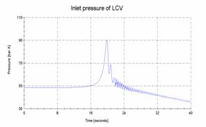 Figure 7. Pressure pick upstream of Steam
generator level control valves - head limiter of main pumps available
Figure 7. Pressure pick upstream of Steam
generator level control valves - head limiter of main pumps available
Conclusion
In this paper we tested the capabilities of computational program PIPENET to solve water hammer problems that occur in pipe systems. We started with solving a well know problem from technical literature and comparing the results between numerical calculation with numerical methods (Allievi correlations) and computational program (PIPENET). The differences between differences between methods were insignificant and were generated by the fact that PIPENET take in consideration amortizations caused by fluid viscosity.
After that we made a transient analyze on a complex system: feed water system. This analyze revealed the importance of maximal head protection in order to protect the system against the pressure pick.
We studied nine transient regimes derived from:
valve closing time from 1 to 15 and 24 seconds
overhead protection of the main feed water pumps available and unavailable
warm up line of standby pump available or not
for all 9 regimes we made parametrical analyze for speed o sound, and pipe thickness.
From the results we observed that this protection reduced the pick pressure from 100 bar (g) to about 90.5 bar (g) meaning lowering the maximum pressure under the projecting pressure of the system.
On the other hand we tested the parametric analyze on the response of the system to water hammer phenomena. We varied several parameters as speed of sound, speed of water hammer propagation, pipe thickness, close/open time of the level control valves, availability - unavailability of maximum head of the main pumps. This complex analyze has given us the importance of having a system to check input data for consistency and accuracy and validating of stationary initial regime in order to obtain an accurate system response.
Taking in consideration the very high pressure pick resulting during water hammer phenomena, we conclude that all nuclear systems should be tested to water hammer analyzes in order to obtain the maximum pressure that can occur during abnormal operating of a nuclear power plant.
On the other hand there are measures to be taken in order to limit the effect of water hammer phenomena: inferior limiting of control and operating valves stroke time, not oversize the thickness of the pipe in order to limit the sound speed in the system.
This paper shows importance of transient analyze of a system during design and operating of a system.
Bibliography
[1] Julieta Florea, Gh. Zidaru Bazele hidraulicii - culegere de probleme- -EDP. Bucuresti 1969
[2] Aureliu Leca,
[3] Philip Thomas Simulation of Industrial Processes for Control
Engineers, Butterwoth - Heinemann,
[4] Julieta Florea, M. Panaitescu Mecanica Fluidelor - - Ed. tehnica Bucuresti 1975
[5] *** Feed water system - design manual
[6] *** Pipenet - User Guide
[7] Ilie PRISECARU, Daniel DUPLEAC, Iulian Pavel NITA Thermal hydraulic Modeling and analysis of CANDU Shutdown Cooling System ESMc'2006
[8] Ilie PRISECARU, Daniel DUPLEAC and Adrian Constantinescu CanDU
[9] Asteapta Dupleac
|
Politica de confidentialitate |
| Copyright ©
2026 - Toate drepturile rezervate. Toate documentele au caracter informativ cu scop educational. |
Personaje din literatura |
| Baltagul caracterizarea personajelor |
| Caracterizare Alexandru Lapusneanul |
| Caracterizarea lui Gavilescu |
| Caracterizarea personajelor negative din basmul |
Tehnica si mecanica |
| Cuplaje - definitii. notatii. exemple. repere istorice. |
| Actionare macara |
| Reprezentarea si cotarea filetelor |
Geografie |
| Turismul pe terra |
| Vulcanii Și mediul |
| Padurile pe terra si industrializarea lemnului |
| Termeni si conditii |
| Contact |
| Creeaza si tu |